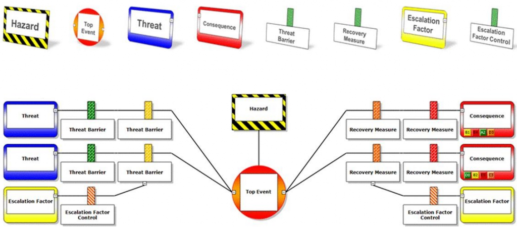
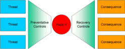
Services

TSC believes in high Quality, Cost Effective and Timely performed Work.

Hazard & Operability Studies (HAZOP)

Hazard and Operability (HAZOP) studies are undertaken by the application of a formal, systematic, and critical approach to examine the process and engineering intentions of a process design. A hazard and operability study (HAZOP) is a structured and systematic examination of a complex planned or existing process or operation in order to identify and evaluate problems that may represent risks to personnel or equipment. The intention of performing a HAZOP is to review the design to pick up design and engineering issues that may otherwise not have been found. The technique is based on breaking the overall complex design of the process into a number of simpler sections called 'nodes' which are then individually reviewed. It is carried out by a suitably experienced multi-disciplinary team (HAZOP) during a series of meetings. The HAZOP technique is qualitative, and aims to stimulate the imagination of participants to identify potential hazards and operability problems. The HAZOP technique was initially developed in the 1960s to analyze major chemical process systems but has since been extended to other areas, including mining operations and other types of process systems and other complex systems such as nuclear power plant operation and software development. It is also used as the basis for reviewing Batch processes and operating procedures

The potential for hazard is thus assessed, and the chances of malfunction of individual equipment and its consequences for a whole system, are identified. The examination of the design is structured by using deviations from the design intent using a specific set of guidewords. This ensures complete coverage of all possible problems while allowing sufficient flexibility for an imaginative approach.

The main objectives of the HAZOP is to :-

1) Review the engineering with the objective of identifying potential hazard or operability problems.
2) Offer recommendations to eliminate or mitigate the identified problems and identify areas that require further study.

safety

Hazard Identification (HAZID), Hazard & Effect Register (H&E) and MAH Register, Environmental Aspects Identification (ENVID)

The objectives of the HAZID procedure is to identify main hazards, to review the effectiveness of selected safety measures and, where required, to expand the safety measures in order to achieve a tolerable residual risk for facility safety concepts for new installations and also where safety concepts of existing operational facilities have to be reviewed. The analysis serves the operator as proof that installations are operated such that hazards for employees, third parties, the environment and the surroundings can largely be excluded. The operator’s management gets an up-to-date picture of the present hazards and their possible effects.
The ENVID (Environmental issues Identification) is a tool, which provides a structured and high-level approach to the identification of environmental and social risk from the earliest stages of an opportunity, and is part of environmental and social risk management framework (although the term ‘ENVID’ is used, socioeconomic and community health issues are often also addressed alongside the environment). The ENVID can ultimately be viewed as the key interface tool between the EIA and the Environmental Engineering processes with regard to a project or development.


The following are the advantage of HAZID and ENVID

  • Identify opportunities for inherent safety
  • Identify Dangerous release scenarios and measure to prevent it.
  • Any special preparations required to be taken
  • Any specific process modifications if required can be established at an early stage.
  • Prepares the system & team, ready and confident to go ahead for commissioning. Avoids major surprises at the end
  • Hazards involved in operating each equipments can be enlisted at the beginning, leading to better process mapping
  • The major benefit of HAZID is early identification and assessment of the critical health, safety and environmental hazards provides essential input to the project development decision


safety

Hazards and Effect register is a guide where a company list all hazards associated with the operation. Each company will have a unique hazards register because each company is unique. It is very useful tool and help in understanding the hazards and mitigation at one location from different studies.

Safety Integrity Levels (SIL) assessment, Verification & Validation

SIL is an exercise in risk analysis where the risk associated with a specific hazard, that is intended to be protected against by a SIF, is calculated without the beneficial risk reduction effect of the SIF. That "unmitigated" risk is then compared against a tolerable risk target. The difference between the "unmitigated" risk and the tolerable risk, if the "unmitigated" risk is higher than tolerable, must be addressed through risk reduction of the SIF. This amount of required risk reduction is correlated with the SIL target.

The main objective of the SIL is to identify and verify the required integrity levels based on Health/Safety, Environmental and Financial considerations using the SIL Risk Assessment Matrix. The study shall be based on IEC 61508/61511. SIL study is typically carriedout inline with HAZOP Study and most of the same people are used for the SIL study. IEC 61511 standard requires that a safety lifecycle (divided into three main phases, i.e. the analysis phase, the implementation or realization phase, and the operation/maintenance phase) be followed. IEC 61511 lifecycle approach also emphasizes that management of functional safety and functional safety assessment, safety lifecycle structure and planning, and verification activities continuously occur throughout all phases of the safety lifecycle.

Simultaneous Operations (SIMOPS) & Matrix of Permitted operations (MOPO)

SIMOPS is short for "simultaneous operations." It is pretty much applied to any situation where two different activities are occurring close enough to each other that there is a risk of interference, clashing, or risk transfer. Multiple vessels operating in the same area, but on different missions or serving different roles, is a good example of SIMOPS. It is an effective tool and aids in planning, monitoring and managing complex operations especially during modification/ expansion at existing facilities.
The MOPO is a set of matrices that maps operational activities against foreseeable situations that if or when they arise, could compromise safe operating limits – these situations are identified from the Threats and Escalation Factors identified for high risk hazards and an assessment of other operations and activities that could contribute to the escalation of an incident, e.g. continuing with hot work when fire pumps (a safety critical element (SCE)) are unavailable. MOPO is usually the outcome of SIMOPS.

The objectives of the SIMOPS are:

  1. Identify and systematically assess the hazards associated with simultaneous production and construction activities
  2. Make recommendations to reduce the risk associated with those activities
  3. Develop a SIMOPS matrix as a reference to production and construction personnel as to which activities need special precautions/ restrictions/ controls to minimise the risk to life, production, assets and environment
  4. To issue a detailed report on SIMOPS study of SIMOPS workshop for the implementation of the workshop outcome and way forward.
  5. To ensure outcome of the SIMOPS assessment are taken as an input into safety studies
  6. To prepare and issue a SIMOPS Plan and send for Approval.

There are following stages in SIMOPS study:

  1. Identification of project phases
  2. Identification of SIMOPS Activities related to each project phase
  3. Identification of Hazards/threats/concerns during SIMOPS activities
  4. Identification of control methods, restrictions, precautions etc. for each project phase/activities
  5. Development/update of SIMOPS Matrix MOPO.

Project Health Safety & Environmental Review (PHSER)

PHSER is carried out to ascertain that sensitive areas have been identified and that the engineering and operational procedures, including those for occupational HSE control for the project have been developed to control the identified risks. The PHSER is not a guarantee that the installation will meet these objectives.

The objective of a PHSER team is to conduct a qualitative audit at a level of enquiry which generally avoids getting involved in detail. The responsibility for design, construction and commissioning of facilities rests at all times with the pre-Project and Project organizations, including the contractors involved, acting on behalf of the owner. The responsibility for subsequent operation rests with the owner. Any aspects which the PHSER team consider unsatisfactory must be referred back to the Project or the owner for action

The advantages of the PHSER are given below:-

  1. PHSER is a structured approach to examining the HSE Risks.
  2. An Audit of Project procedures and their implementation to ensure compliance with HSE standards
  3. Acts as a basis for participation of employees within the company
  4. Provide assurance to stack-holders that all sensitive areas of HSE risks have been identified and appropriate mitigation measures are taken

Design Reviews

Design review is an independent review of the design intent of an engineered system or process, as defined by documented standards. The scope of review will normally include structures, vessels, pipelines, and safety systems. The review process also aims to identify errors or failures in the design (or operation) of the engineered systems and processes at early stages. In order to evaluate a Design against its requirements, a number of means may be considered, such as:

  1. Physical tests.
  2. Engineering simulations.
  3. Examinations (Walk-through)

Design work can roughly be divided into three stages: early conceptual work, mid-stage mock and prototype creation and late-stage build. Each of these stages maps to a different part of a product: problem, solution, and implementation. An effective design thoroughly addresses the underlying problem, the expression of a solution in UI, and the implementation of that solution. It’s a multilayered stack that should add up to a design that supports your ultimate goals.

Bow-tie Analysis

The Bowtie method is a risk evaluation method that can be used to analyze and demonstrate causal relationships in high risk scenarios. The method takes its name from the shape of the diagram that is created, which looks like a men’s bowtie. A Bowtie diagram does two things. First of all, a Bowtie gives a visual summary of all plausible accident scenarios that could exist around a certain Hazard. Second, by identifying control measures the Bowtie display what a company does to control those scenarios.

The advantages of the Bow tie analysis are given below:

  1. Bow tie analysis is very effective for initial Process Hazard Analysis
  2. Ensures identification of high probability and high consequence events
  3. Combined application of a high-level fault/event trees
  4. Representation of the causes of a event and the measures in place to prevent and mitigate hazards
  5. Evaluation of Safeguards
  6. Understanding of Scenario in one complete diagram

Fire Explosion and Risk Analysis (FERA)/Quantitative and Qualitative Risk Assessment (QRA)

FERA/QRA is the art and science of developing and understanding numerical estimates of the risk (i.e., combinations of the expected frequency and consequences of potential accidents) associated with a facility or operation. It uses a set of highly sophisticated, but approximate tools for acquiring risk understanding. The primary purposes of a QRA study are as follows:

  1. To assess the risks to personnel, assets, and Environment posed by the facilities and. This helps in to decide how best the risks can be reduced;
  2. Comparing risks with design options that being considered. This helps identifying design options with low risk, and selecting the option which is best from a risk point of view.
  3. LSIR contours can be used for land use planning
  4. Assess the societal risk associated with the facility.

The various steps in the FERA/QRA process are described below.

  1. Data Collection and Sorting
  2. Hazard Identification
  3. Identification of Measure Risk Contributor
  4. Consequence Analysis
  5. Failure Frequency Analysis
  6. Calculation of Individual & Societal Risk
  7. Comparison to Risk Acceptance Criteria ,
  8. ALARP Demonstration through identified Risk Reduction Measures (RRM) if Risk falls in ALARP region
  9. Recommendations

Escape Evacuation and Rescue Analysis (EERA)

The Escape, Evacuation, and Rescue Analysis (EERA) is tool in which we qualitatively examine and evaluate the effectiveness of Evacuation and Rescue systems available with the facility. The followings must be taken into consideration of a EERA:-

  1. Set desired goals and objectives for the facilities;
  2. Identify escape, evacuation and rescue facilities provided for personnel to escape from the immediate effects, and, if necessary, evacuate the facility and spot an ultimate safe place.
  3. Identify accident scenarios and their consequence and incorporate in EERA
  4. Determination of availability of escape routes,
  5. Determine the minimum endurance time required of the EER facilities based on estimating time of muster and evacuation and evaluate against the basis of design and assess whether the defined EER goals and objectives are met, and if not, suitable and cost benefited recommendations shall be provided based on Best industry practices.


Thermal Radiation and Flare/Vent Dispersion Studies

Thermal radiation is electromagnetic radiation generated by the thermal motion of charged particles in matter. All matter with a temperature greater than absolute zero emits thermal radiation. When the temperature of a body is greater than absolute zero, inter-atomic collisions cause the kinetic energy of the atoms or molecules to change. This results in charge-acceleration and/or dipole oscillation which produces electromagnetic radiation, and the wide spectrum of radiation reflects the wide spectrum of energies and accelerations that occur even at a single temperature.

A flare or vent system collects and discharges gas from atmospheric or pressurized process components to the atmosphere to safe locations for final release during normal operations and abnormal conditions (emergency relief). In vent systems, the gas exiting the system is dispersed in the atmosphere. Flare systems generally have a pilot or ignition device that ignites the gas exiting the system because the discharge may be either continuous or intermittent. Gas-disposal systems for tanks operating near atmospheric pressure are often called atmospheric vents or flares, and gas-disposal systems for pressure vessels are called pressure vents or flares. A flare or vent system from a pressurized source may include a control valve, collection piping, flashback protection, and a gas outlet. A scrubbing vessel should be provided to remove liquid hydrocarbons.

The objective of the thermal radiation and Flare/Vent dispersion study are the following

  1. Vent/Flare is a very critical equipment and play a major role especially in emergency/abnormal scenario
  2. Make working environment and neighborhood safe
  3. Can be used for land use planning
  4. Vent/Flare height can be fixed adequately for safe dispersion and no damage to other equipment due to thermal radiation

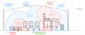
Hazardous Area Classification (HAC) Reviews

A hazardous area is defined as three-dimensional space in which a flammable atmosphere may be expected to be present at such frequencies as to acquire special precautions for the design and construction of equipment, and the control of other potential ignition sources. All other areas are non-hazardous in this context, though they may, in part or whole, form part of a wider restricted area within the facility in which all work is carried out under special controls. The areas are subdivided into zones based on the likelihood of occurrence and duration of a flammable atmosphere, as follows:

ZONE 0: The part of a hazardous area in which flammable atmosphere is continuously present or present for long periods.

ZONE 1: The part of a hazardous area in which a flammable atmosphere is likely to occur in normal operation.

ZONE 2: The part of a hazardous area in which a flammable atmosphere is not likely to occur in normal operation and, if it occurs, will exist only for a short period.

Non-Hazardous areas: Areas that do not fall into any of the above Zones.
Hazardous area locations are created when flammable gases, liquids and vapours and/or combustible dusts are generated, prepared, processed, handled, stored, transferred or otherwise used.
Explosives hazardous areas are created when explosive substances are manufactured, prepared, processed, handled, stored, transferred or otherwise used.

“Explosion Protection” is the name given to the globally recognised techniques used to prevent the ignition of flammable materials and combustible dusts within hazardous area locations by electrical equipment.
When electrical equipment is used in, around, or near an atmosphere that has flammable gases or vapors, flammable liquids, combustible dusts, there is always a possibility or risk that a fire or explosion might occur. Those areas where the possibility or risk of fire or explosion might occur due to an explosive atmosphere and/or mixture is often called a hazardous (or classified) location/area.
Hazardous locations per the Class/Division system are classified according to the Class, Division, and Group. 1. Class—The Class defines the general nature (or properties) of the hazardous material in the surrounding atmosphere which may or may not be in sufficient quantities.
a. Class I—Locations in which flammable gases or vapors may or may not be in sufficient quantities to produce explosive or ignitable mixtures.
b. Class II—Locations in which combustible dusts (either in suspension, intermittently, or periodically) may or may not be in sufficient quantities to produce explosive or ignitable mixtures.
c. Class III—Locations in which ignitable fibers may or may not be in sufficient quantities to produce explosive or ignitable mixtures.
HAC and methods of performing HAC have been around in various national standards for a long time already. In some European countries (e.g. Belgium) HAC is required under existing law.

Our assessments include:

      • Identification of flammable materials,
        potential release sources and local ventilation within the plant 
      • Classification of the hazardous areas 
        associated with each potential release source, based on the appropriate standards 
      • Preparation of a Report of the assessment 
        describing the techniques applied and any specific issues.
      • Preparation of a Schedule of the materials 
        that might be release to create hazardous areas 
      • Preparation of a Schedule of the potential release sources 
        within the plant and the associated Hazardous Area zones.


GLC Modelling

The concentration in air of a pollutant to which a human being is normally exposed, i.e. between the ground and a height of some 2 metres above it.

Air quality models are used to predict ground level concentrations down point of sources. The object of a model is to relate mathematically the effects of source emissions on ground level concentrations, and to establish that permissible levels are, or are not, being exceeded. Models have been developed to meet these objectives for a variety of pollutants and time circumstances.

Models may be described according to the chemical reactions involved. So-called nonreactive models are applied to pollutants such as CO and SO2 because of the simple manner in which their chemical reactions can be represented. Reactive models address complex multiple-species chemical mechanism common to atmospheric photochemistry and apply to pollutants such as NO, NO2, and O3.

Models can be described as simple or advanced based on the assumptions used and the degree of sophisticated with which the important variables are treated. Advanced models have been developed for such problems as photochemical pollution, dispersion in complex terrain, long-range transport, and point sources over flat terrain. The most widely used models for predicting the impact of relative unreactive gases, such as SO2, released from smokestacks are based on Gaussian diffusion.

In Gaussian models, the spread of a plume in vertical horizontal directions is assumed to occur by simple diffusion along the direction of the mean wind. The maximum ground level concentration is calculated by means of the following Equation.


Consequence Analysis

Consequence Analysis refers to the calculation or estimation of numerical values (or graphical representations of these) that describe the credible physical outcomes of loss of containment scenarios involving flammable, explosive and toxic materials with respect to their potential impact on people, assets, or safety functions. It quantifies vulnerable zone for a conceived incident and once the vulnerable zone is identified for an incident, measures can be proposed to eliminate damage to plant and potential injury to personnel. The objective of  the Consequence Analysis are to prepare for emergency in advance.

Environmental Impact Assessments

Environmental Impact Assessment (EIA) is a process of evaluating the likely environmental impacts of a proposed project or development, taking into account inter-related socio-economic, cultural and human-health impacts, both beneficial and adverse.

The purpose of the assessment is to ensure that decision makers consider the environmental impacts when deciding whether or not to proceed with a project. The International Association for Impact Assessment (IAIA) defines an environmental impact assessment as "the process of identifying, predicting, evaluating and mitigating the biophysical, social, and other relevant effects of development proposals prior to major decisions being taken and commitments made. EIAs are unique in that they do not require adherence to a predetermined environmental outcome, but rather they require decision makers to account for environmental values in their decisions and to justify those decisions in light of detailed environmental studies and public comments on the potential environmental impacts


The structure of a generic Environmental Assessment is as follows:

  1. Summary
  2. Introduction
    • Background
    • Purpose and Need for Action
    • Proposed Action
    • Decision Framework
    • Public Involvement
    • Issues
  3. Alternatives, including the Proposed Action
    • Alternatives
    • Mitigation Common to All Alternatives
    • Comparison of Alternatives
  4. Environmental Consequences
  5. Consultation and Coordination